Purpose
Many building plans have wall dimensions displayed to the center of the wall. This feature provides the ability to create walls by inputting the dimension as they are on the plan, and will reduce the need for manual calculations.
Steps

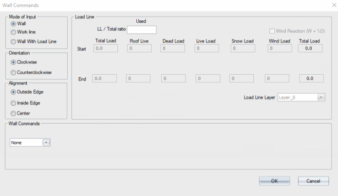
- Select Wall Commands from the Walls menu.
The Wall Commands dialog displays.
-
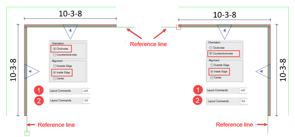
Clockwise creates walls from right to left, in a clockwise direction; counterclockwise inputs walls from left to right, in a counterclockwise direction.
-
Alignment can be one of the following, with walls placed in reference to an reference line :
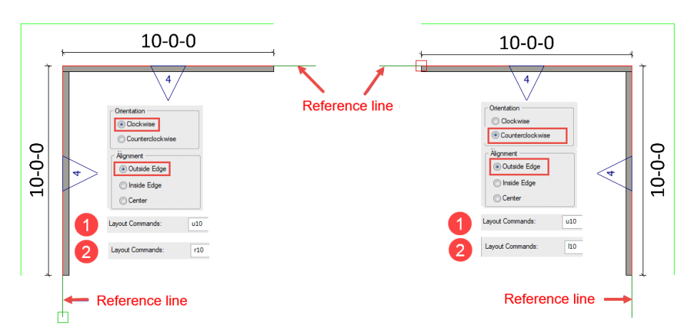
3. Enter a direction and distance in the Layout Commands text box.
The following examples illustrate the different alignment options.
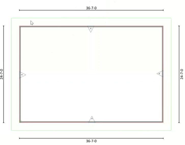
The following 24' x 36' structure was created by entering a direction and distance in the Layout Commands text box on the main workspace.
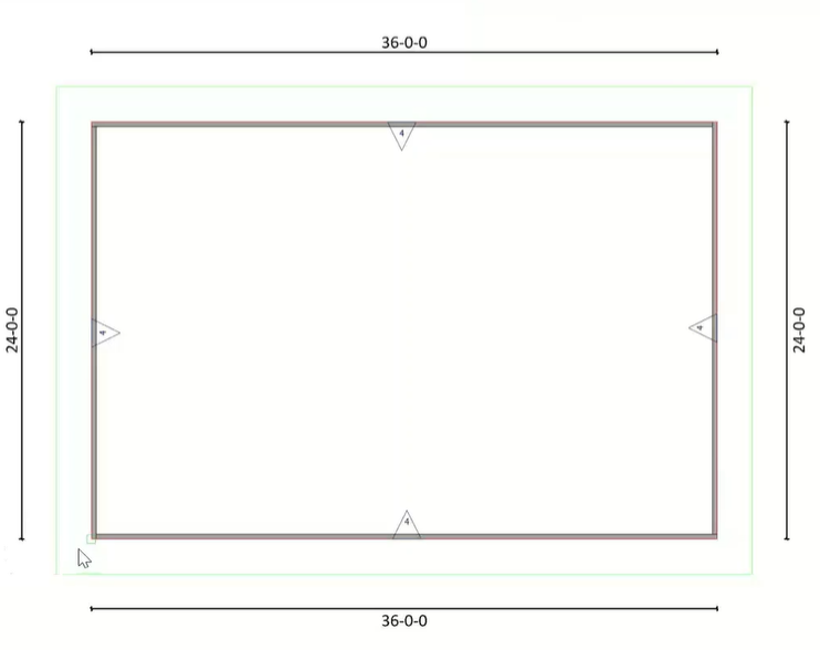
When Outside Edge is selected, the wall is placed with its outside edge at the reference line.
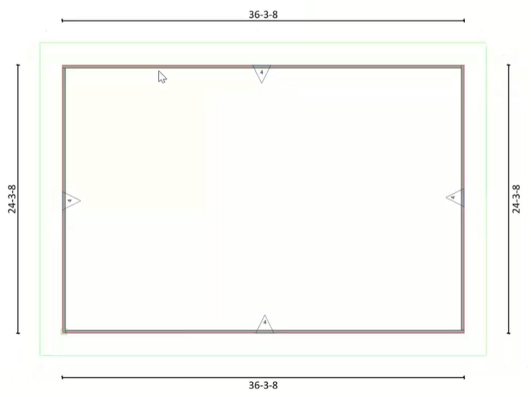
When Inside Edge is selected for a 24' x 36' structure, the difference in the new wall width is added to or subtracted from the inside of the wall, so that the outside edge of the wall remains at the original reference line.
When Inside Wall is selected, the wall is placed with its inside edge at the reference line.
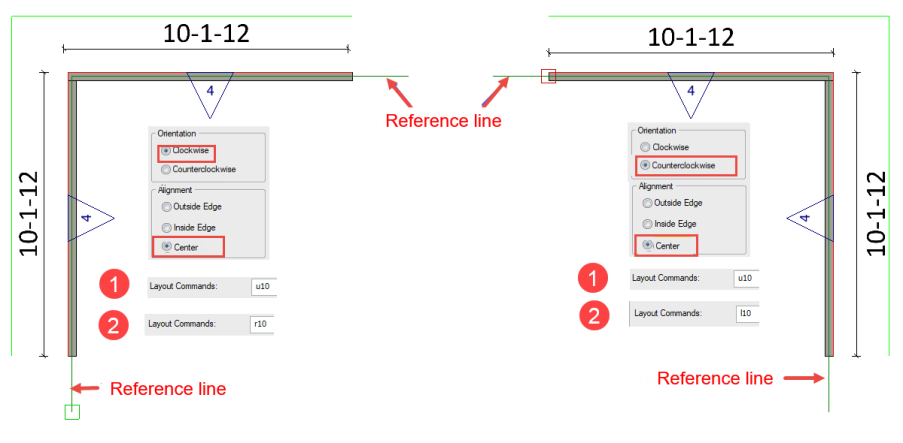
When Center is selected, the wall is centered on the reference line.
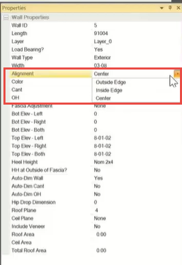
You can easily change the alignment in the Properties pane.